0%

DP IB Physics: HL

Topic Questions

Home / IB / Physics: HL / DP / Topic Questions / 5. Electricity & Magnetism / 5.3 Electric Cells / Structured Questions


5.3 Electric Cells

Question 1a

Marks: 2

Cells used in circuits can be divided into two groups, primary cells and secondary cells.

(a)
Define a primary cell and state an example.
   
[2]
    Assess your score
      

    Question 1b

    Marks: 3
    (b)
    Define a secondary cell and state an example.
       
    [3]
      Assess your score
        

      Question 1c

      Marks: 2

      For the following descriptions of the functions of primary and secondary cells, choose the correct words from each pair in bold to complete the sentences.

      (c)
      During normal operation of a primary cell, the electrons flow from the negative/positive plate of the cell, around the circuit, to the negative/positive plate of the cell.
         
      When recharging a secondary cell, the electrons are forced from the negative/positive plate to the negative/positive plate by an external current.
      [2]
        Assess your score
          

        Question 1d

        Marks: 2

        Lithium cells are widely used and have allowed for a revolution in the manufacture of portable electronics. However there are concerns with reliance on lithium as a material for making cells.

        (d)
        Outline two concerns with the use of lithium in cells.
            
        [2]
          Assess your score
            

          Question 2a

          Marks: 3

          The electromotive force, ε is defined by the equation 

          epsilon space equals space I space left parenthesis R space plus space r right parenthesis

          (a)
          Define the following variables and state an appropriate unit for each.
               
          (i)
          I
          [1]
          (ii)
          R
          [1]
          (iii)
          r
          [1]
            Assess your score
              
            Key Concepts
            Electromotive Force

            Question 2b

            Marks: 5

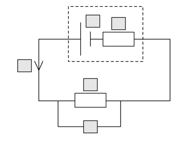
            The circuit shown includes a cell with internal resistance and a load resistor.

            easy-sq-5-4-q-2b-circuit-qun

            (b)
            Complete the labels on the components using each of the following variables once only.
               

            ε

            I

            r

            R

            V

            [5]

              Assess your score
                
              Key Concepts
              Internal Resistance

              Question 2c

              Marks: 3

              A current of 0.6 mA flows through the circuit in part (a) and the resistor has a resistance of 2.5 kΩ.

              5-3-q2c-circuit-qun-sl-sq-easy-phy

              (c)
              Calculate the terminal potential difference VT  of the circuit.
                  
              [3]
                Assess your score
                  

                Question 2d

                Marks: 3

                The internal resistance of the cell is 1.3 kΩ. 

                (d)
                Calculate the emf of the cell.
                   
                [3]
                  Assess your score
                    

                  Question 3a

                  Marks: 4
                  (a)

                  Explain what is meant by the electromotive force of a cell and state the units.

                      [4]

                    Assess your score
                      
                    Key Concepts
                    Electromotive Force

                    Question 3b

                    Marks: 1
                    (b)
                    Define the internal resistance of a cell.
                       
                    [1]
                      Assess your score
                        
                      Key Concepts
                      Internal Resistance

                      Question 3c

                      Marks: 2

                      In the circuit shown a high resistance voltmeter is used to measure the potential difference across the terminals of a battery.

                      q2c-figure-1

                        
                      (c)
                      The switch is closed.

                      (i)
                      State how the voltmeter reading changes.
                      [1]
                      (ii)
                      Explain what property of the battery causes this change.
                      [1]
                        Assess your score
                          

                        Question 3d

                        Marks: 1
                        (d)
                        Explain why the voltmeter reading changes when the switch is closed.
                            
                        [1]
                          Assess your score
                            

                          Question 4a

                          Marks: 3

                          To investigate the internal resistance and emf of a cell a student uses the circuit shown. The cell has emf ε and internal resistance r and is connected in series to a variable resistor with resistance R.

                          qu-4a-figure-1a

                          The student wishes to determine the relationship between the voltmeter and ammeter readings whilst decreasing R. Their results are given.


                          Terminal potential difference / V

                          Current / A


                          8.3

                          0.07


                          6.8

                          0.17


                          4.6

                          0.33


                          2.9

                          0.44


                          0.3

                          0.63

                          (a)
                          Plot a graph of the data using the graph layout given below.

                          qu-4a-figure-1b
                          [3]
                            Assess your score
                              

                            Question 4b

                            Marks: 2
                            (b)
                            Using your graph from part (a) (or the model solution provided)
                                
                            (i)
                            Determine the value of ε.
                            [1]
                            (ii)
                            Explain your method.
                            [1]
                              Assess your score
                                

                              Question 4c

                              Marks: 4
                              (c)
                              Using your graph from part (a) (or the model solution provided) calculate the value of r. Show your method clearly.
                                 
                              [4]
                                Assess your score
                                  

                                Question 4d

                                Marks: 4
                                (d)
                                Using your graph from part (a) (or the model solution provided) sketch a line to show the results obtained from a cell with:

                                (i)
                                The same emf but larger internal resistance. Label this A.
                                [2]
                                (ii)
                                The same internal resistance but larger emf. Label this B.
                                [2]
                                  Assess your score
                                    

                                  Question 5a

                                  Marks: 6

                                  The circuit shown is used to test a battery of four identical cells each with emf ε = 0.70 V.

                                  qu-5a-figure-1

                                  A fixed resistor with R = 0.62 kΩ is connected in series with the cell. A current I = 4.50 mA travels through the circuit.


                                  (a)
                                  For this circuit

                                  (i)
                                  Calculate the emf of the battery.
                                  [2]
                                  (ii)
                                  Calculate the internal resistance of the battery.
                                  [3]
                                  (iii)
                                  State an appropriate unit for your answer.
                                  [1]
                                    Assess your score
                                      

                                    Question 5b

                                    Marks: 2
                                    (b)
                                    For the circuit in part (a), calculate the internal resistance of one cell.

                                    [2]

                                      Assess your score
                                        
                                      Key Concepts
                                      Internal Resistance

                                      Question 5c

                                      Marks: 4

                                      As cells are used they discharge their voltage, according to a curve as shown.

                                      5-3-q5c-discharge-curve-qun-sl-sq-easy-phy

                                      (c)
                                      To describe the graph, choose the correct word from each pair.

                                      • When a cell is discharging, it will/will not discharge a constant amount of voltage.
                                      • When the cell is new the initial high voltage will begin to discharge slowly/fairly quickly.
                                      • For most of the life of the cell it discharges slowly/fairly quickly.
                                      • Finally, as the cell reaches the end of its life the voltage is discharged slowly/fairly quickly.

                                      [4]

                                        Assess your score
                                          

                                        Question 5d

                                        Marks: 6

                                        The graph in part (c) represents a 1.5 V AA battery discharging over time. The battery is connected so that the circuit draws a current of 2.0 A.

                                        (d)
                                        Using the graph from part (c), add discharge curves for two identical cells which are drawing different currents. Label your lines (i) and (ii).

                                        (i)
                                        Current, I = 1.0 A
                                        [3]
                                        (ii)
                                        Current, I = 4.0 A
                                        [3]
                                          Assess your score