In circuit building a set of agreed symbols is in use worldwide to represent components.
(a)
For each description below, write the name and draw the correct symbol which would be used in a circuit diagram.
(i)
A resistor whose resistance depends on the light intensity.
[2]
(ii)
A component with zero resistance which measures the current in the circuit.
[2]
(iii)
The component which is used to convert ac current to dc current; it also allows current to flow in only one direction.
[2]
Assess your score
View Answer
(b)
In each case select the word to correctly describe an ammeter.
In a circuit the current/voltage/resistance is measured using an ammeter, which is always connected in series/parallel within a circuit.
An ideal ammeter should have very high/zero resistance. This prevents the ammeter taking any energy from the electrons/positive ions flowing through it.
If the electrons transferred their electricity/energy/motion to the ammeter this would change the circuit by reducing/increasing the value of the current it is meant to measure.
[3]
Assess your score
View Answer
A charge of 15.0 C passes through a resistor at a constant rate in 60 s. The potential difference across the resistor is 2.0 V.
(c)
Calculate the resistance R of the resistor.
[3]
Assess your score
View Answer
(d)
The resistance of a wire is affected by factors including the resistivity of the material it is made from.
(i)
Define resistivity.
[2]
(i)
State two other factors apart from temperature which affects the resistance of a wire. For each one identify whether the relationship is directly or inversely proportional to resistance.
[2]
Assess your score
View Answer
Next Question
A student is building a circuit using three resistors, each with a value of 5.0 Ω. The student arranges the resistors first in series and then in parallel, as shown.
(a)
Determine the total resistance in each case.
(i)
Three 5.0 Ω resistors in series
[2]
(ii)
Three 5.0 Ω resistors in parallel
[2]
Assess your score
View Answer
The student arranges the identical 5.0 Ω resistors so that they are in a combination of series and parallel as shown.
(b)
Calculate the new combined resistance.
Assess your score
View Answer
An electrically-conducting wire is made from copper. Copper has resistivity ρ = 1.7 × 10⁻⁸ Ω m.
The wire has diameter d = 2.0 mm and length L = 20 mm as shown.
(c)
For the wire calculate
(i)
The cross-sectional area of the wire
[2]
(ii)
The resistance of the wire
[2]
Assess your score
View Answer
A student investigating the resistivity of a sample of wire has plotted a graph of resistance against length as shown.
(d)
Explain how the graph can be used to determine the resistivity of the wire.
[3]
Assess your score
View Answer
Previous Question Next Question
(a)
Define resistance.
[2]
Assess your score
View Answer
The simple circuit diagram shown illustrates Kirchoff's First Law.
(b)
State the law in words.
[2]
Assess your score
View Answer
(c)
For the circuit shown determine the values on the ammeters. A1 , A2 and A3 .
[3]
Assess your score
View Answer
(d)
For Kirchhoff's second law
(i)
State Kirchhoff's Second Law.
[2]
(ii)
Complete the sentence;
Kirchhoff's First Law is a consequence of the conservation of _____ while Kirchhoff's Second Law is a consequence of the conservation of _____.
[2]
Assess your score
View Answer
Previous Question Next Question
The graph shown represents current and potential difference for an Ohmic resistor.
a)
State the features of the graph which show that the resistor obeys Ohm's Law.
[2]
Assess your score
View Answer
A student investigating the I-V characteristics of various components plots the graph shown.
(b)
Outline how to find the resistance of the component from the graph.
[3]
Assess your score
View Answer
The graph shown represents the I-V characteristics of a non-Ohmic resistor such as a lamp.
(c)
The graph consists of three distinct parts.
(i)
For the section labelled (i) outline the behaviour of the resistor.
[2]
(ii)
For the two similar sections labelled (ii) outline the behaviour of the resistor.
[3]
Assess your score
View Answer
Heating is typically seen in electrical components and must be accounted for so that they operate safely and efficiently.
(d)
State two factors which increase the amount of heat output.
[2]
Assess your score
View Answer
Previous Question Next Question
(a)
For the series circuit shown, calculate
(i)
Total resistance.
[2]
(ii)
Current measured by the ammeter
[2]
Assess your score
View Answer
(b)
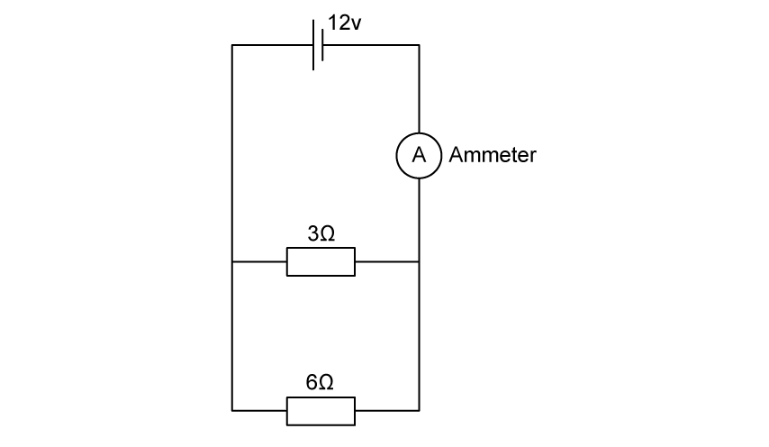
For the parallel circuit shown, calculate
(i)
Total resistance.
[2]
(ii)
Current measured by the ammeter
[2]
Assess your score
View Answer
The potential divider circuit shown is to be adapted to become a sensing circuit for temperature.
(c)
Suggest a change which would enable this.
[2]
Assess your score
View Answer
The sensing circuit in part (c) has been built using a thermistor placed in parallel to the output voltage, with a fixed resistor R1 of 100 Ω, and an input voltage, Vin of 220 V as shown.
At a certain temperature the thermistor has resistance R2 = 20 Ω.
(d)
Determine the output voltage at this temperature.
[3]
Assess your score
View Answer
Previous Question


