Kirchhoff's Circuit Laws
Kirchhoff's First Law
- Kirchhoff’s first law states that:
The sum of the currents entering a junction always equals the sum of the currents out of the junction
- A junction is a point where at least three circuit paths meet

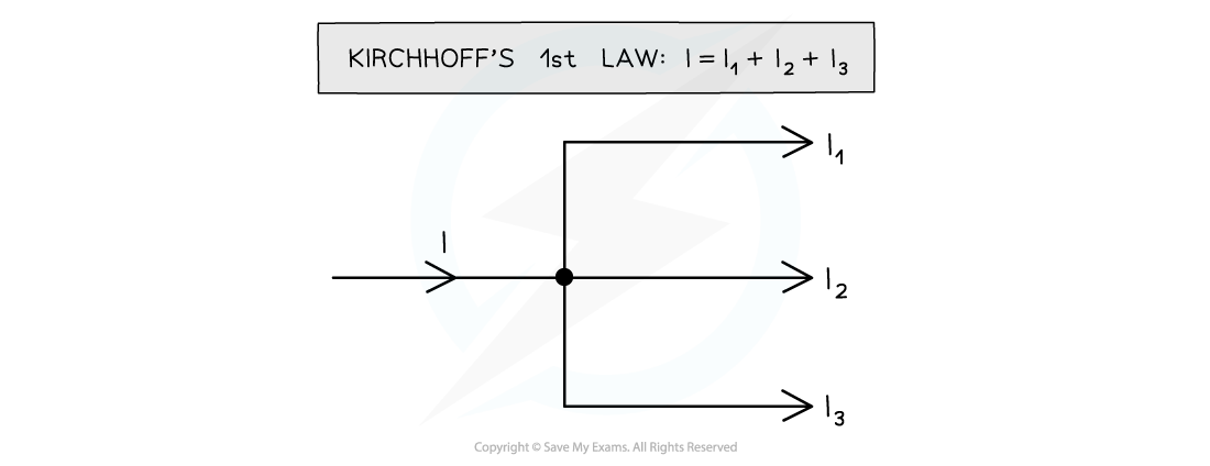
The current I into the junction is equal to the sum of the currents I1, I2 and I3 out of the junction
- Kirchhoff’s first law is a consequence of conservation of charge
- The charge is the same on both sides of the junction
- Kirchhoff’s first law is often written as follows:
∑I = 0
- Where:
- ∑I = net current entering and leaving the junction
- The current entering a junction is defined as positive
- The current leaving a junction is defined as negative
Worked Example
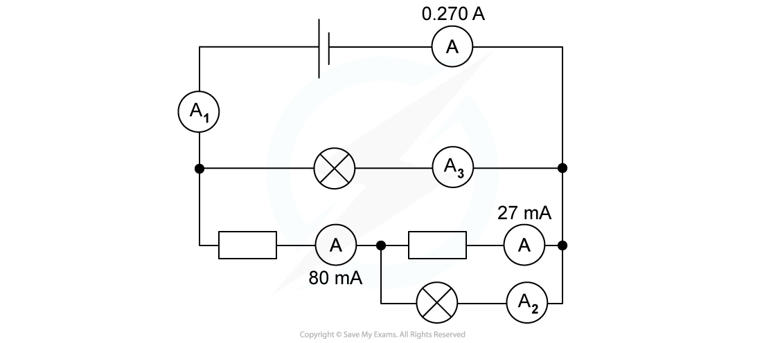
For the circuit below, state the readings of ammeters A1, A2 and A3.
Step 1: Ammeter A1 is in series with ammeter A
- The current reading of ammeter A1 is the same as that of ammeter A
A1 = 0.270 A
Step 2: From Kirchhoff's first law, the total current entering the junction must be equal to the total current leaving the junction
- The current from ammeter A1 enters a junction and splits into two branches
- One branch has a current of 80 mA = 0.080 A
- The current in the other branch is the reading of ammeter A3
0.270 A = 0.080 A + A3
A3 = (0.270 – 0.080) A = 0.19 A
Step 3: Apply Kirchhoff's law to the other junction of the circuit
- The 0.080 A current enters a junction and splits into two branches
- One branch has a current of 27 mA = 0.027 A
- The current in the other branch is the reading of ammeter A2
0.080 A = 0.027 A + A2
A2 = (0.080 – 0.027) A = 0.053 A
The current readings of the three ammeters are:
- A1 = 0.270 A = 270 mA
- A2 = 0.053 A = 53 mA
- A3 = 0.19 A = 190 mA
Kirchhoff's Second Law
- Kirchhoff’s second law states that:
The net potential difference in a closed loop is equal to zero
- This is a consequence of conservation of energy
- The electric potential energy carried by the electrons as they flow through a circuit must be equal to the overall thermal energy transferred to the different components

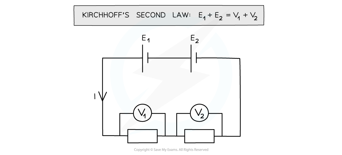
The sum of the electric potential energies E1 and E2 provided by the two cells must be equal to the sum of the potential differences across the two fixed resistors
- Kirchhoff’s second law is often written as follows:
∑V = 0
- Where:
- ∑V = net potential difference in a closed loop
- The potential difference entering a cell is defined as positive
- The potential difference entering a resistor (or another circuit component offering resistance) is defined as negative
Worked Example
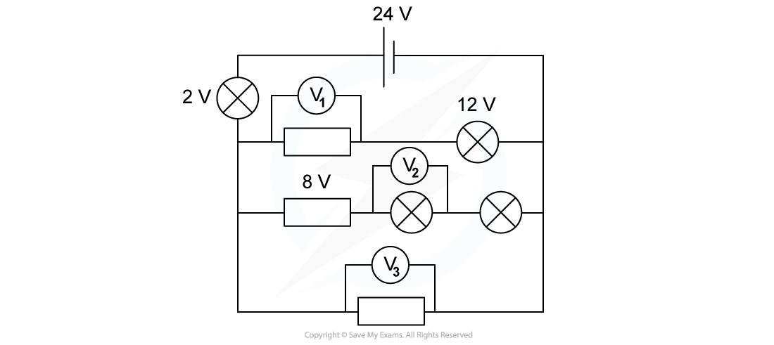
For the circuit below, state the readings of the voltmeters V1, V2 and V3.All the lamps and resistors have the same resistance.
Step 1: Kirchhoff's second law states that the sum of all potential differences in the first loop is equal to zero
- The potential difference provided by the cell is positive and equal to 24 V
- The potential difference across the first light bulb is negative and equal to 2V
- The potential difference across the second light bulb is negative and equal to 12 V
V1 = (24 – 2 – 12) V = 10 V
Step 2: Apply Kirchhoff's second law to the second loop of the circuit
- The potential difference across the fixed resistor is negative and equal to 8 V
- The potential difference across each light bulb is negative and equal in value to the reading of V2 (since they have the same resistance)
- All these negative potential differences must be summed to:
- The positive potential difference provided by the cell (24 V)
- The negative potential difference across the light bulb connected in series with the cell (2 V)
2V2 = (24 – 2 – 8) V = 14 V
V2 = 7 V
Step 3: Apply Kirchhoff's second law to the third loop of the circuit
- The reading of V3 is equal to the sum of:
- The positive potential difference provided by the cell (24 V)
- The negative potential difference across the light bulb connected in series with the cell (2 V)
- The reading of V3 is equal to the sum of:
V3 = (24 – 2) V = 22 V
The potential difference readings of the three voltmeters are:
- V1 = 10 V
- V2 = 7 V
- V3 = 22 V
Exam Tip
Kirchhoff's first and second laws are given in the data booklet, so you do not need to memorise them. However, you need to apply them to both simpler and more complex circuits.
