Circuit Diagrams
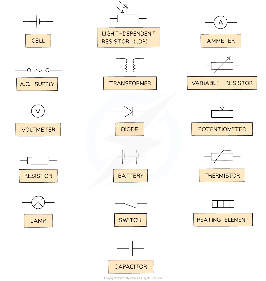
- The diagram below shows the various circuit symbols that could be used in circuit diagrams

Common circuit symbols
Functions of Most Common Components
- Switch: it turns the circuit on (closed), or off (open)
- Fixed resistor: it limits the flow of current
- As electrons flow through a resistor, they transform electrical potential energy into other forms of energy (i.e. thermal energy)
- Variable resistor: a resistor with a slider that can be used to change its resistance
- As the resistance of the variable resistor increases, the current in the circuit decreases and vice versa
- Thermistor: a resistor whose resistance depends on its temperature
- As temperature increases, the resistance of a thermistor decreases and vice versa
- Light-dependent resistor (LDR): a resistor whose resistance depends on the light intensity
- As light intensity increases, the resistance of a LDR decreases and vice versa
- Diode: it allows current to flow in one direction only
- It is often use for rectification - i.e. conversion of AC into DC
- Light-emitting diode (LED): it emits light when a current passes through it
- Light bulb: a resistor that transforms electric potential energy into such large thermal energy that energy is dissipated as light emitted to the surroundings
- Ammeter: it measures the current in the circuit
- Voltmeter: it measures the potential difference of an electrical component
Worked Example
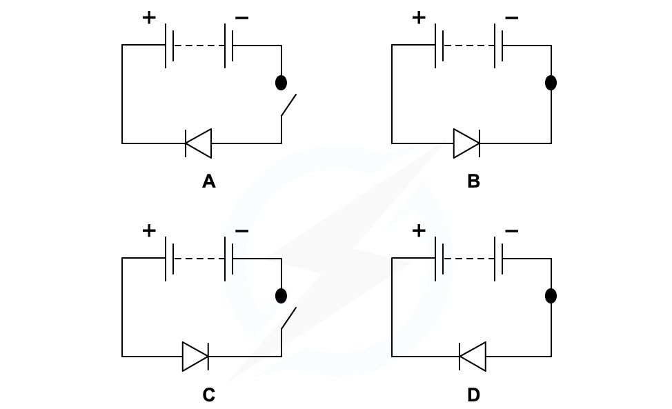
Which circuit diagram correctly represents a circuit with current flowing through?

- For a circuit to be connected, the switch must be closed
- This is either circuit B or D
- The other circuit symbol is a diode
- Diodes only allow current to flow in one direction
- Since current flow is from positive to negative, a forward-biased diode must point in this direction in order for the current to flow
- This is seen in circuit B
Exam Tip
The standard circuit symbols are given in the data booklet, so you do not need to memorise them. However, you must be able to identify them and draw them correctly.
Ammeters & Voltmeters
Measuring Current
- Electric current is measured using an ammeter
- Ammeters should always be connected in series within a circuit

To measure the current flowing through a light bulb, an ammeter must be connected in series with it
- An ideal ammeter should have zero resistance
- This way, it will not take any energy from the electrons flowing through it
- Otherwise it would alter the value of the current it is trying to measure
Measuring Potential Difference
- Potential difference (or voltage) is measured using a voltmeter
- A voltmeter is always set up in parallel to the component whose voltage is being measured
- This means that the voltmeter must be hooked across the terminals of the component

To measure the potential difference of a fixed resistor, a voltmeter must be connected in parallel to it
- When electrons flow through a component in the circuit (e.g. a resistor):
- They transfer some of their electrical potential energy to it
- The component transforms this electrical potential energy into some other form of energy (e.g. thermal)
- Measuring the potential difference across a component means comparing the value of the electric potential energy of the electrons before they enter the component to when they leave it
