Capacitance
- Capacitors are electrical devices used to store energy in electronic circuits, commonly for a backup release of energy if the power fails
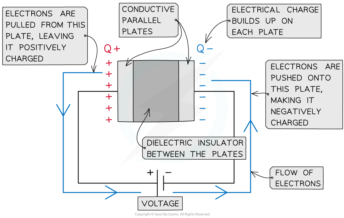
- They are in the form of two conductive metal plates connected to a voltage supply (parallel plate capacitor)
- There is commonly a dielectric in between the plates, this is to ensure charge does not freely flow between the plates
- The capacitor circuit symbol is:

The capacitor circuit symbol is two parallel lines

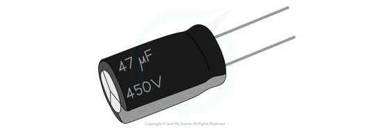
A capacitor used in small circuits
- Capacitors are marked with a value of their capacitance. This is defined as:
The charge stored per unit potential difference (between the plates)
- The greater the capacitance, the greater the energy stored in the capacitor
- The capacitance of a capacitor is defined by the equation:
- Where:
- C = capacitance (F)
- q = charge (C)
- V = potential difference (V)
- Capacitance is measured in the unit Farad (F)
- In practice, 1 F is a very large unit
- Often it will be quoted in the order of micro Farads (μF), nanofarads (nF) or picofarads (pF)
- If the capacitor is made of parallel plates, Q is the charge on the plates and V is the potential difference across the capacitor
- The charge Q is not the charge of the capacitor itself, it is the charge stored on the plates
- This capacitance equation shows that an object’s capacitance is the ratio of the charge stored by the capacitor to the potential difference between the plates
Worked Example
A parallel plate capacitor has a capacitance of 1 nF and is connected to a voltage supply of 0.3 kV.
Calculate the charge on the plates.
Step 1: Write down the known quantities
-
- Capacitance, C = 1 nF = 1 × 10⁻⁹ F
- Potential difference, V = 0.3 kV = 0.3 × 10³ V
Step 2: Write out the equation for capacitance
Step 3: Rearrange for charge Q
q = CV
Step 4: Substitute in values
q = (1 × 10-9) × (0.3 × 103) = 3 × 10⁻⁷ C = 300 nC
Electric Field in a Parallel Plate Capacitor
- A parallel plate capacitor is made up of two conductive metal plates connected to a voltage supply
- An assumption made for these types of capacitors is that their length of the plates is much greater than their separation
- The negative terminal of the voltage supply pushes electrons onto one plate, making it negatively charged
- The electrons are repelled from the opposite plate, making it positively charged
- There is commonly a dielectric in between the plates, this is to ensure charge does not freely flow between the plates

A parallel plate capacitor is made up of two conductive plates with opposite charges building up on each plate
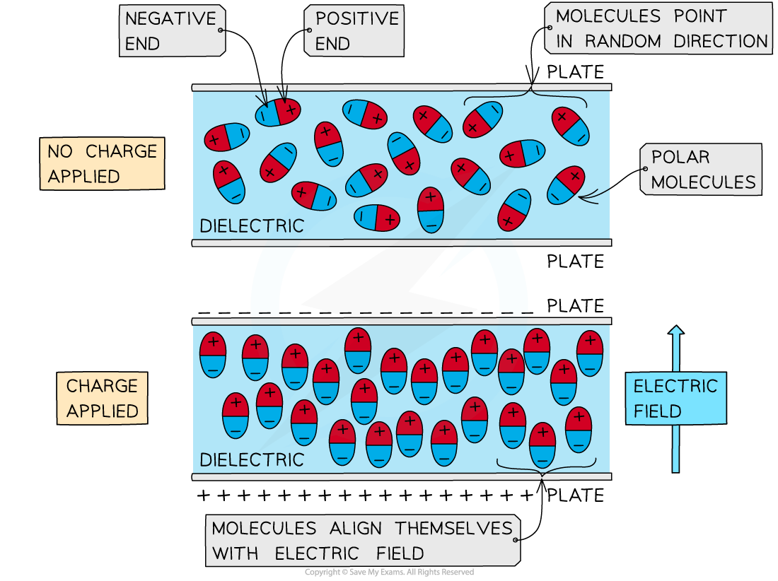
- A dielectric is made up of many polar molecules
- These are molecules that have a 'positive' and 'negative' end (poles)
- When no charge is applied to the capacitor:
- There is no electric field between the parallel plates and the molecules are aligned in random directions
- When there is a charge applied:
- One of the parallel plates becomes positively charged and the other negatively charged hence an electric field is generated between the plates (from positive to negative)
- The negative ends of the polar molecules are attracted to the positive plate and vice versa
- This means all the molecules rotate and align themselves parallel to the electric field

Polar molecules align themselves when an electric field is between two parallel plates
Exam Tip
The ‘charge stored’ by a capacitor refers to the magnitude of the charge stored on each plate in a parallel plate capacitor or on the surface of a spherical conductor. The capacitor itself does not store charge.
The letter ‘C’ is used both as the symbol for capacitance as well as the unit of charge (coulombs). Take care not to confuse the two!
