Electromotive Force
- When charge passes through a power supply such as a battery, it gains electrical energy
- The electromotive force (e.m.f) is the amount of chemical energy converted to electrical energy per coulomb of charge (C) when charge passes through a power supply
- e.m.f is measured in Volts (V)

Definition of e.m.f with regards to energy transfer
- e.m.f is also the potential difference across the cell when no current is flowing
- e.m.f can be measured by connecting a high-resistance voltmeter around the terminals of the cell in an open circuit

e.m.f is measured using a voltmeter connected in parallel with the cell
EMF & Potential Difference
- The difference between potential difference and e.m.f is the type of energy transfer per unit charge

Definition of potential difference with regards to energy transfer
- When charge passes through a resistor, for example, its electrical energy is converted to heat in the resistor
- The resistor, therefore, has a potential difference across it
- Potential difference describes the loss of energy from charges; ie. when electrical energy is transferred to other forms of energy in a component
- e.m.f. describes the transfer of energy from the power supply to electrical charges within the circuit
Exam Tip
Although voltage and potential difference are the same thing, make sure not to confuse them with e.m.f, which is slightly different!
Internal Resistance
- All power supplies have some resistance between their terminals
- This is called internal resistance (r)
- This internal resistance causes the charge circulating to dissipate some electrical energy from the power supply itself
- This is why the cell becomes warm after a period of time
- The internal resistance therefore causes loss of voltage or energy loss in a power supply
- A cell can be thought of as a source of e.m.f with an internal resistance connected in series. This is shown in the circuit diagram below:
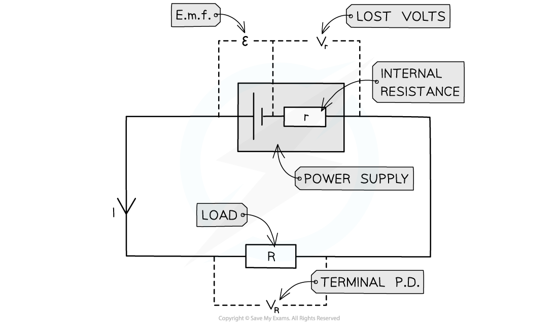
Circuit showing the e.m.f and internal resistance of a power supply
- Where:
- Resistor R is the ‘load resistor’
- r is the internal resistance
- ε is the e.m.f
- Vr is the lost volts
- VR is the p.d across the load resistor, which is the same as the terminal p.d
- The e.m.f is the sum of these potential differences, giving the equation below

e.m.f equation
- e.m.f is therefore the total, or maximum, voltage available to the circuit
Worked Example
A battery of e.m.f 7.3 V and internal resistance r of 0.3 Ω is connected in series with a resistor of resistance 9.5 Ω. Determine:
a) The current in the circuit
b) Lost volts from the battery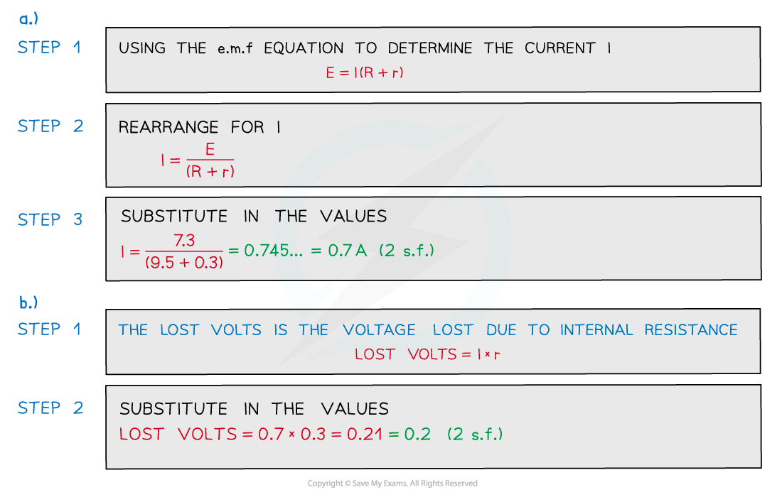
Determining Internal Resistance
Aims of the Experiment
The overall aim of the experiment is to investigate the relationship between e.m.f and internal resistance by measuring the variation of current and voltage using a variable resistor
Variables
- Independent variable = voltage, V (V) & current, I (A)
- Dependent variable = resistance, R (Ω)
- Control variables:
- E.m.f of the cell
- Internal resistance of the cell
Equipment List
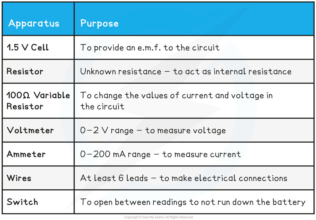
- Resolution of measuring equipment:
- Voltmeter = 1 mV
- Ammeter = 0.1 mA
Method

- The cell and the resistor, labelled r, should be connected in series and considered to be a single cell
- With the switch open, record the reading V on the voltmeter
- Set the variable resistor to its maximum value, close the switch and record V and the reading I on the ammeter - make sure to open the switch between readings
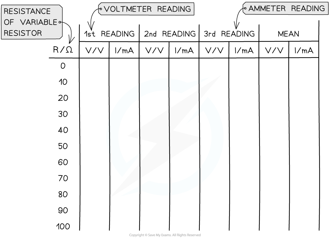
- Vary the resistance of the variable resistor up to a minimum of 8-10 readings and record values for V and I for each resistance. Ensure to take readings for the whole range of the variable resistor
- An example of a suitable table might look like this:
Analysing the Results
- The relationship between e.m.f. and internal resistance is given by
ε = I (R + r)
- Where:
- ε = electromotive force (V)
- I = current (A)
- R = resistance of the load in the circuit (Ω)
- r = internal resistance of the cell (Ω)
- This can be simplified into the form:
ε = IR + Ir = V + Ir
- Rearranging this equation for V:
V = –rI + ε
- Comparing this to the equation of a straight line: y = mx + c
- y = V (V)
- x = I (A)
- Gradient = –r (Ω)
- Y-intercept = ε (V)
- Plot a graph of V against I and draw a line of best fit
- Measure the gradient of the graph and compare it with the manufacturer’s value of the resistor
- The y-intercept will be the e.m.f and the gradient will be the negative internal resistance:

Evaluating the Experiment
Systematic Errors:
- Only close the switch for as long as it takes to take each pair of readings
- This will prevent the internal resistance of the battery or cell from changing during the experiment
Random Errors:
- Only use fairly new cells otherwise the e.m.f. and internal resistance of run-down batteries can vary during the experiment
- Wait for the reading on the voltmeter and ammeter to stabilise (stop fluctuating) before recording the values
- Take multiple repeat readings (at least 3) for each voltage and current and calculate a mean to reduce random errors
Safety Considerations
- This is a very safe experiment, however, electrical components can get hot when used for a long period
- Switch off the power supply right away if burning is smelled
- Make sure there are no liquids close to the equipment, as this could damage the electrical equipment
Worked Example
In an experiment, a student uses a variable resistor as an external load. The current flowing through the circuit is measured with a suitable milliammeter and the potential difference across the variable resistor is measured with a voltmeter for a range of resistance values.The data collected was as follows: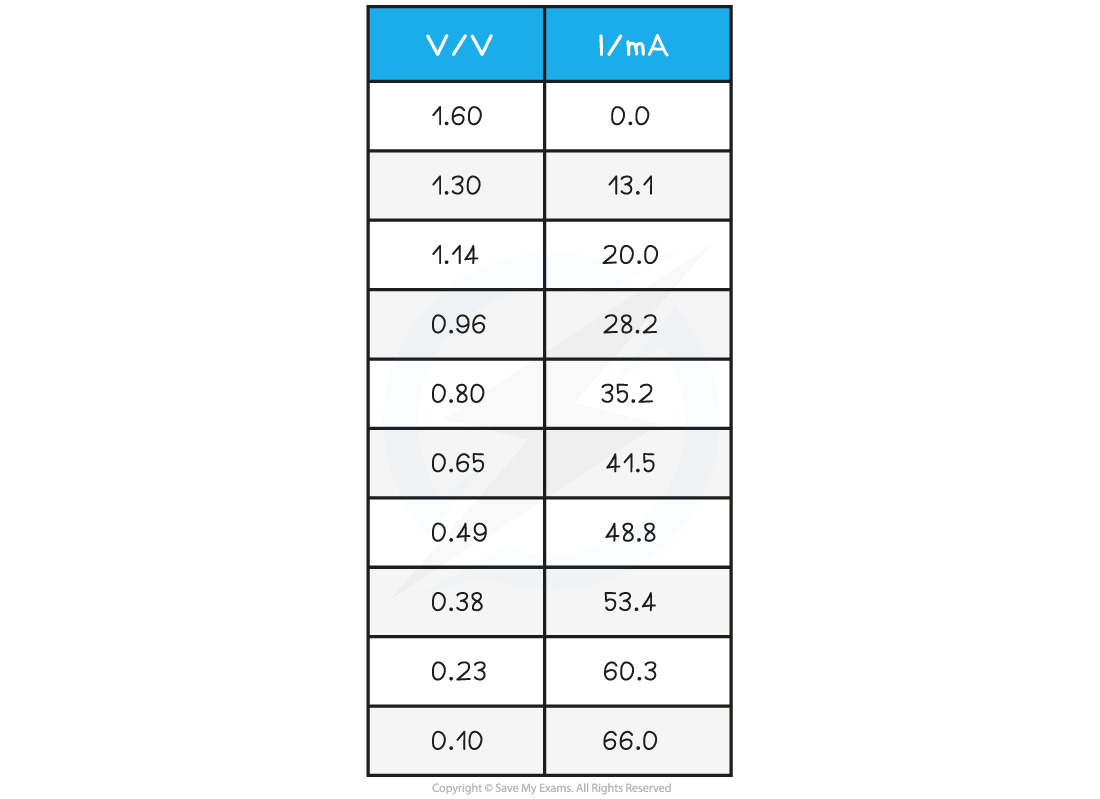 Plot a graph of these results and determine the e.m.f. and the internal resistance directly from the graph.
Step 1: Plot the data on a graph of V against I and draw a line of best fit

Step 2: Draw the largest triangle possible in order to calculate the gradient

 Step 3: Determine the e.m.f. and the internal resistance from the graph
V = –rI + E
- From this equation:
- Gradient = –r (Ω)
- Y-intercept = E (V)
- Therefore:
- Internal resistance, r = 22.7 Ω
- E.m.f. E = 1.60 V
