Capacitors

Capacitors are electrical components used in circuits requiring timing or smoothing. They store charge, which is then released at a rate that can be controlled.


Key Concepts

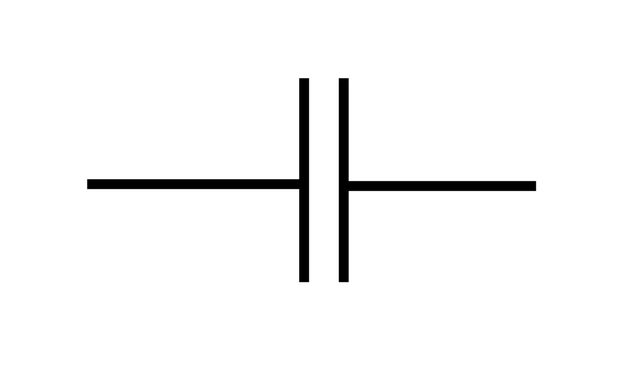
A capacitor consists of two parallel plates separated by a dielectric material. Current cannot flow through the dielectric; instead, charge is stored on the plates. The circuit symbol of a capacitor is effective!
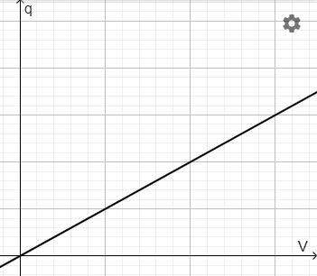
The capacitance of a capacitor is defined as the ratio of the charge stored to the potential difference across the capacitor:

\(C={q\over V}\)

  • \(C\) is capacitance (F)
  • \(q\) is charge (C)
  • \(V\) is potential difference (V)

For a fixed capacitance, \(q=CV\). Capacitance can be determined from the gradient of a charge-potential difference graph.
Work done and charge

The work required to add charges to already charged plates increases with the charge stored.

It is not only parallel plates that can store charges. A sphere can also store charge.

Energy stored

The energy stored when a capacitor is charged can be calculated by adding the infinitesimal stages of work done when each new quantity of charge is added. This is equal to the area under the graph. Since charge stored is proportional to the potential difference across the capacitor:

\(E={1\over 2}qV\)

\(\Rightarrow E={1\over 2}CV^2\)

  • \(E\) is the energy stored on the capacitor or the work done that was required to store the charges (J)

Charging and discharging

Circuit diagram

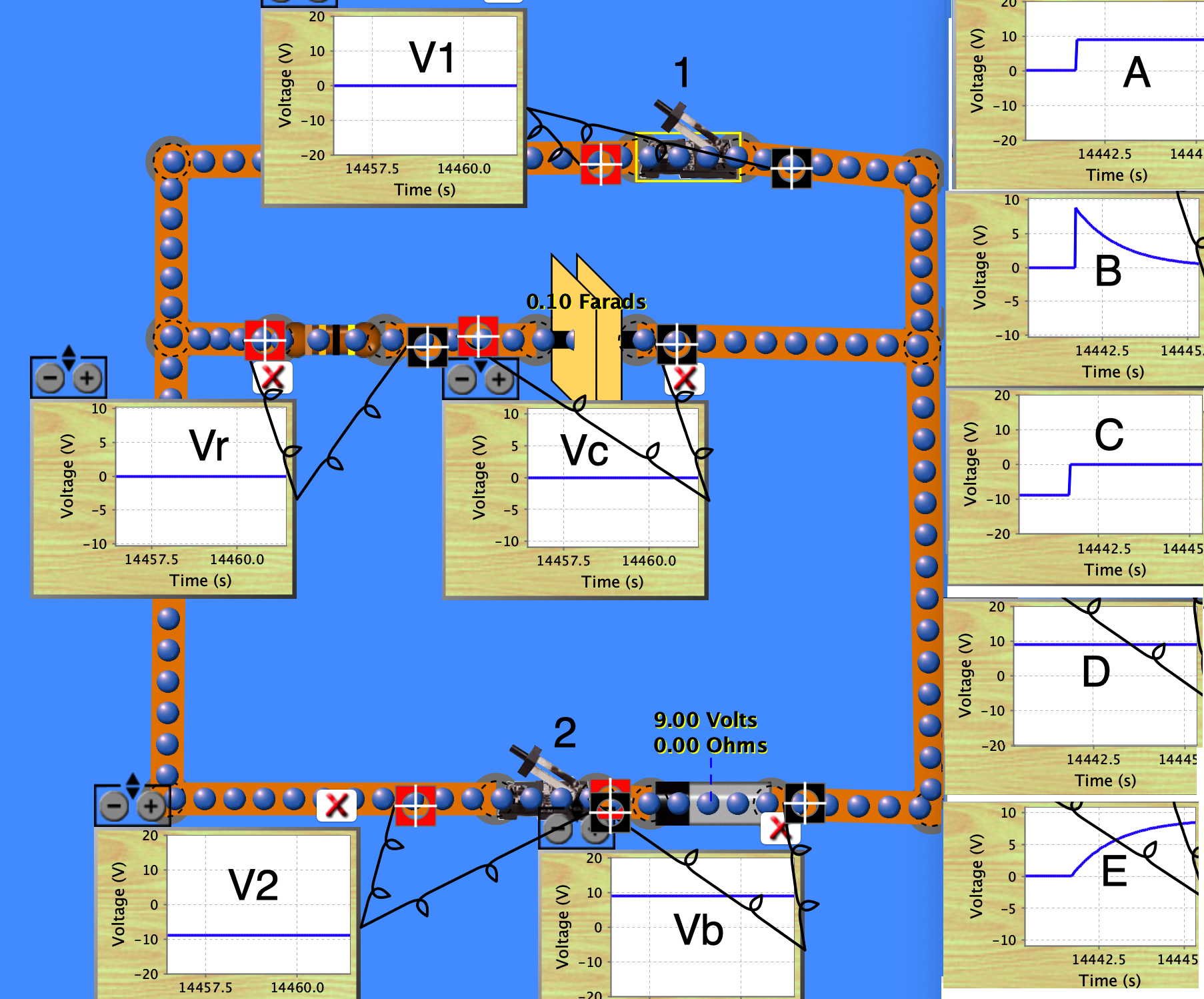
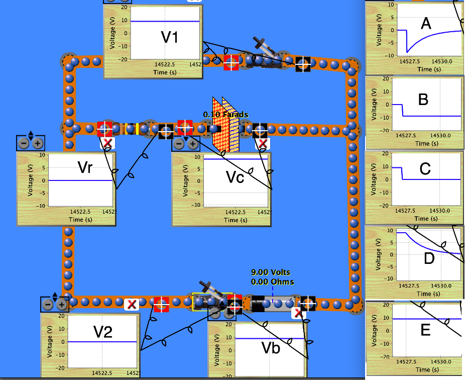
Capacitors are charged when connected in series with a power supply (position A in the diagram below). The charge stored is at a maximum when the potential difference on the capacitor rises to match the power supply. At this point, no current flows.

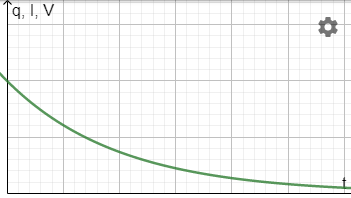
Capacitors discharge through a given resistor when not connected to a power supply (position B). The current is maximum at first. As the charge stored on the capacitor decreases, so does the potential difference across it. The current falls.

Exponential relationships

The repelling nature of the charges stored has the effect that the rate of discharge from a capacitor is proportional to the charge remaining on a capacitor. Mathematically, \(-{\mathrm{d}q\over \mathrm{d}t}\propto q\). Expressions for the variation of charge, current and potential difference with time can be derived:

\(q=q_0e^{-t\over \tau}\)

\(I=I_0e^{-t\over \tau}\)

\(V=V_0e^{-t\over \tau}\)

  • \(q\) is the remaining charge stored on the capacitor (C)
  • \(q_0\) is the initial charge stored on the capacitor (C)
  • \(I\) is the current (A)
  • \(I_0\) is the initial current (A)
  • \(V\) is the potential difference across the capacitor (C)
  • \(V_0\) is the initial potential difference across the capacitor (C)
  • \(t\) is the time over which the capacitor has been discharging (s)
  • \(\tau\) is the time constant (s)

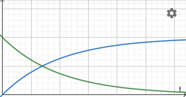
These equations are exponential decay relationships and have the following characteristic shape when plotted against time:

When a capacitor is charged:

  • the charge stored and potential difference increase (blue)
  • current decreases (green)

Time constant

The time constant for a capacitor circuit is defined as the time taken for the charge, current or potential difference to fall to \(1\over e\) of their original value. This is approximately \(0.37q_0\)\(0.37I_0\) or \(0.37 V_0\).

The time constant can be found from the graph in one of two ways:

  • Moving down the vertical axis to find \(0.37q_0\), etc, and then going across to the curve and down to the time.
  • Drawing a tangent to the curve at \(t=0\) and extrapolating until it cuts the time axis.

Time constant also has a real-world meaning. It is the product of the capacitance and load resistance (for the circuit diagram shown above):

\(\tau=RC\)

  • \(\tau\) is time constant (s)
  • \(R\) is load resistance (\(\Omega\))
  • \(C\) is capacitance (F)

Combinations

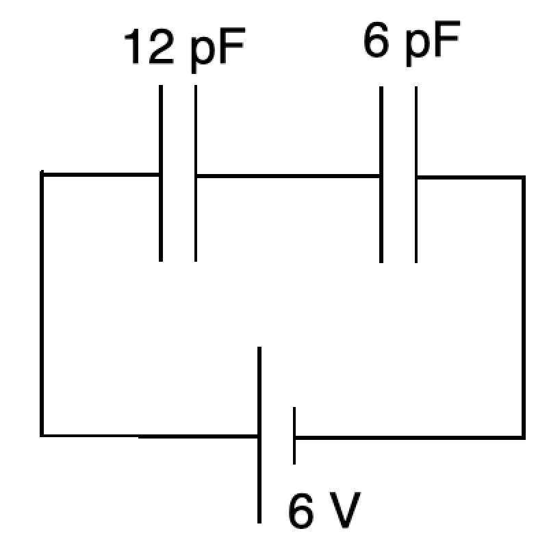
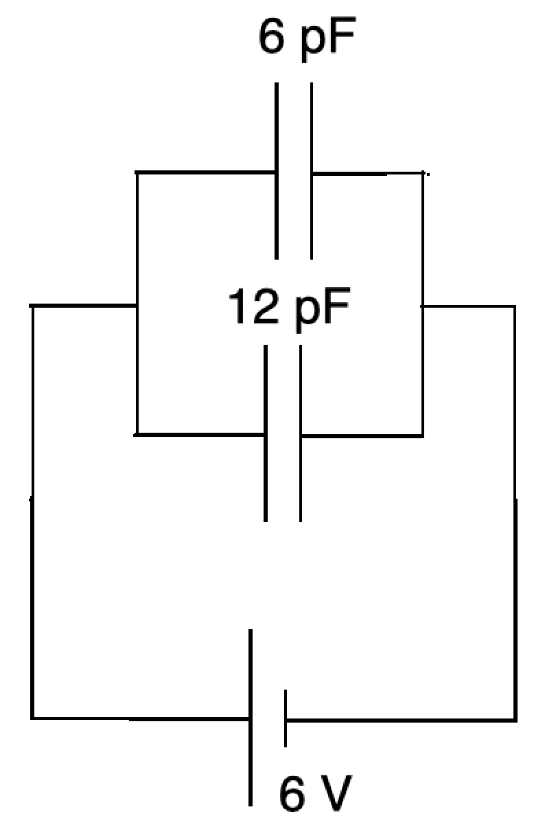
Like other circuit components, capacitors can be connected in series and in parallel.

In parallel, the potential difference on each capacitor is in the same direction; each stores charge in the same orientation. The total capacitance for capacitors in parallel is the sum of the individual capacitances:

\(C_\text{parallel}=C_1+C_2+...+C_n\)

In series, the capacitors counteract one another. The total capacitance is less than any individual capacitor:

\({1\over C_\text{series}}={1\over C_1}+{1\over C_2}+...+{1\over C_n}\)

Essentials

A capacitor contains a uniform electric field. The value of the capacitance of a capacitor is set according to three variables:

\(C=\varepsilon{A\over d}\)

  • \(C\) is capacitance (F)
  • \(\varepsilon\) is an electric constant (Fm−1)
  • \(A\) is the area of overlap of the two plates (m2)
  • \(d\) is the separation between the plates (m)

The electric constant is the product of the permittivity of free space and the relative permittivity of the dielectric:

\(\varepsilon=\varepsilon_0k\)

  • \(\varepsilon_0\) is the permittivity of space (8.854 x 10⁻¹² Fm-1)
  • \(k\) is the permittivity of the dielectric (~1 for air and >1 for all media)

Area and distance between the plates

The capacitance of a capacitor can be increased by:

  • increasing the area of the plates (often achieved using a spiral shape)
  • decreasing the separation of the plates

A common exam question will alter the plate separation once they have already been charged. Work is done to separate the attracting plates.

Another common question involves charging or discharging the capacitor with constant current - watch out! These are easy to deal with. Simply revert to the usual equations, such as \(I={q\over t}\).

Effect of the dielectric

The nature of the dielectric material also affects the capacitance. 


Summary

Rectification

Capacitors can be used in rectification to overcome the sinusoidal limitation of full wave diode rectification. The presence of a capacitor in parallel with the load smooths the current through the resistor by continuing to release charge even when the EMF across the power supply falls to zero. This has a smoothing effect.

This bridge circuit can appear to be complex at first. However, tracing the flow of current upward from the power supply through A, D, R, C, B and back to the bottom of the power supply shows that diode bias is adhered to throughout.

Wien bridge circuit

Just as a Wheatstone bridge circuit enabled determination of an unknown resistance, a Wien bridge circuit can be used to determine an unknown capacitance.

Test Yourself

Use quizzes to practise application of theory.

Capacitance


START QUIZ!

Charging and discharging capacitors


START QUIZ!
MY PROGRESS

How much of Capacitors have you understood?