| Date | November 2010 | Marks available | 3 | Reference code | 10N.2.SL.TZ0.A3 |
| Level | Standard level | Paper | Paper 2 | Time zone | Time zone 0 |
| Command term | Draw | Question number | A3 | Adapted from | N/A |
Question
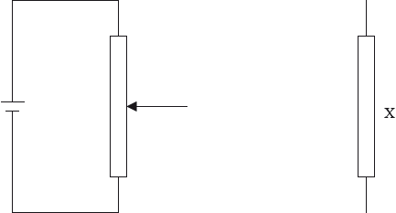
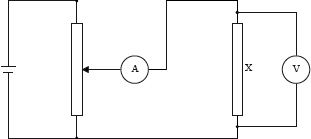
Draw the complete diagram of the circuit that uses a potential divider, ammeter, voltmeter and cell to measure the current-voltage characteristics for component X.
The graph shows the current-voltage characteristics for the component X.
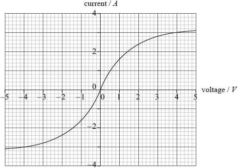
Component X is now connected across the terminals of a cell of emf 2.0 V and negligible internal resistance. Use the graph to show that the resistance of X is \({\text{0.83 }}\Omega \).
Markscheme
voltmeter in parallel across X;
ammeter in series with X;
correct circuit; (allow ecf from 1st and 2nd marking points)
Accept voltmeter connections that include ammeter (in series with X)
Condone re-drawing of resistor X closer to variable resistor.
\(I = 2.4{\text{ A}}\) at 2.0 V;
\(\frac{2}{{2.4}}\);
\( = 0.83{\text{ }}\Omega \)
Award [1 max] for use of gradient of graph from (2,2.4) to origin.
Examiners report
Circuit diagrams of the potential divider were very poor although most were able to predict the correct positions for the ammeter and voltmeter.
Most candidates achieved full marks here.
Syllabus sections
- 17N.2.SL.TZ0.3c: Draw a circuit diagram to show how you could measure the resistance of the carbon-film...
- 17N.2.SL.TZ0.3b: The current direction is now changed so that charge flows vertically through the...
- 17N.2.SL.TZ0.3a.iii: State why knowledge of quantities such as resistivity is useful to scientists.
- 17N.2.SL.TZ0.3a.ii: The film must dissipate a power less than 1500 W from each square metre of its surface to...
- 17N.2.SL.TZ0.3a.i: The resistance of the carbon film is 82 Ω. The resistivity of carbon is 4.1 x 10⁻⁵ Ω m....
- 17N.1.SL.TZ0.18: Kirchhoff’s laws are applied to the circuit shown. What is the equation for the dotted...
- 17N.1.SL.TZ0.17: In the circuit shown, the fixed resistor has a value of 3 Ω and the variable resistor can be...
- 17M.3.SL.TZ2.2a: An ammeter and a voltmeter are connected in the circuit. Label the ammeter with the letter A...
- 17M.2.HL.TZ2.6b.iii: Determine the power dissipated in the cable per unit length.
- 17M.2.HL.TZ2.6b.ii: Calculate the peak current in the cable.
- 17M.2.HL.TZ2.6b.i: Calculate the radius of each wire.
- 17M.2.HL.TZ1.4a.iii: Calculate the power dissipated in the cable.
- 17M.2.SL.TZ2.5b.ii: There is a current of 730 A in the cable. Show that the power loss in 1 m of the cable is...
- 17M.2.SL.TZ1.4c: The heater changes the temperature of the water by 35 K. The specific heat capacity of water...
- 17M.2.SL.TZ1.4b: Explain, in terms of electrons, what happens to the resistance of the cable as the...
- 17M.2.SL.TZ1.4a.ii: Calculate the resistance of the cable.
- 17M.2.SL.TZ1.4a.i: Calculate the current in the copper cable.
- 17M.1.SL.TZ2.20: A circuit contains a cell of electromotive force (emf) 9.0 V and internal resistance 1.0 Ω...
- 17M.1.SL.TZ1.15: Two pulses are travelling towards each other. What is a possible pulse shape when the...
- 16N.2.SL.TZ0.7b: Components R and T are placed in a circuit. Both meters are ideal. Slider Z of the...
- 16N.2.SL.TZ0.7a: (i) State how the resistance of T varies with the current going through T. (ii) Deduce,...
- 16M.2.HL.TZ0.6a: Two cells of negligible internal resistance are connected in a circuit. The top cell has...
- 16M.2.SL.TZ0.5a: State what is meant by an ideal voltmeter.
- 16M.2.SL.TZ0.1e: The electric motor is connected to a source of potential difference 120V and draws a current...
- 16N.1.SL.TZ0.20: A cell of emf 4V and negligible internal resistance is connected to three resistors as shown....
- 16N.1.SL.TZ0.19: An electrical circuit is shown with loop X and junction Y. What is the correct expression...
- 16M.1.HL.TZ0.12: A circuit consists of a cell of electromotive force (emf) 6.0V and negligible...
- 16M.1.SL.TZ0.20: A circuit consists of a cell of electromotive force (emf) 6.0V and negligible internal...
- 16M.1.SL.TZ0.19: The graph shows the variation of current I in a device with potential difference V across...
- 15M.1.SL.TZ2.18: The diagram shows a circuit used to investigate internal resistance of a cell. The...
- 15M.1.SL.TZ1.18: Four resistors are connected as shown. What is the total resistance between X and Y? A. 3...
- 15M.1.HL.TZ2.17: The diagram shows an electric circuit containing a potentiometer of maximum resistance R. The...
- 15M.2.SL.TZ2.5f: An electric circuit consists of a supply connected to a 24Ω resistor in parallel with a...
- 15M.2.HL.TZ2.9a: A 24Ω resistor is made from a conducting wire. (i) The diameter of the wire is 0.30 mm and...
- 15M.2.HL.TZ2.9b: An electric circuit consists of a supply connected to a 24Ω resistor in parallel with a...
- 14M.1.SL.TZ1.16: Each of the resistors in the arrangements below has resistance R. Each arrangement is...
- 14M.1.SL.TZ1.17: Two resistors of resistance 10 Ω and 20 Ω are connected in parallel to a cell of negligible...
- 14M.1.SL.TZ1.18: A battery of emf 12 V and negligible internal resistance is connected to a resistor of...
- 14M.1.SL.TZ2.17: Which of the following is a statement of Ohm’s law? A. The resistance of a conductor is...
- 14M.1.SL.TZ2.18: Three identical filament lamps W, X and Y are connected in the circuit as shown. The cell has...
- 15N.1.HL.TZ0.18: A filament lamp and a semiconducting diode have the voltage–current (\(V\)–\(I\))...
- 15N.2.HL.TZ0.8f.ii: Calculate the power supplied to the transformer.
- 15N.1.SL.TZ0.20: Three resistors of resistance \(R\) are connected in parallel across a cell of electromotive...
- 15N.2.HL.TZ0.8f.i: Calculate the current in the cables connected to the town
- 15N.2.HL.TZ0.8f.iii: Determine the input voltage to the transformer if the power loss in the cables from the power...
- 15N.1.SL.TZ0.19: A cylindrical resistor of length \(l\) is made from a metal of mass \(m\). It has a...
- 15N.2.HL.TZ0.9g.ii: Each cubic metre of the wire contains approximately \(8.5 \times {10^{28}}\) free electrons....
- 14N.1.SL.TZ0.16: A cylindrical resistor of volume V and length l has resistance R. The resistor has a uniform...
- 15N.2.SL.TZ0.6d: An ammeter and a voltmeter are used to investigate the characteristics of a variable resistor...
- 15N.2.SL.TZ0.6e: Show that the current in the circuit is approximately 0.70 A when \(R = 0.80{\text{ }}\Omega \).
- 14N.1.SL.TZ0.18: A lamp is connected to an electric cell and it lights at its working voltage. The lamp is...
- 14N.1.HL.TZ0.19: A voltmeter of resistance 50kΩ is used to measure the electric potential difference in a...
- 14N.1.HL.TZ0.18: A lamp is connected to an electric cell and it lights at its working voltage. The lamp is...
- 14N.2.HL.TZ0.8d.i: On the graph, sketch the variation of \(V\) with \(I\) for the cell.
- 14N.2.HL.TZ0.8d.ii: Using the graph, determine the current in the circuit.
- 14N.2.SL.TZ0.2b.i: Draw on the diagram the positions of the ammeter and voltmeter.
- 14N.2.SL.TZ0.2b.ii: Show that the emf of the cell is 1.25 V.
- 14N.2.SL.TZ0.2b.iv: Calculate the energy dissipated per second in the variable resistor.
- 11N.1.SL.TZO.16: A cell is connected in series with a 2.0Ω resistor and a switch. The voltmeter is connected...
- 11N.1.HL.TZ0.21: A resistor has a resistance R. The potential difference across the resistor is V. Which of...
- 12N.1.SL.TZ0.19: An ideal ammeter is used to measure the current in a resistor. Which of the following gives...
- 12N.1.HL.TZ0.20: An ideal ammeter is used to measure the current in a resistor. Which of the following gives...
- 13N.1.SL.TZ0.17: A resistor X of resistance R is made of wire of length L and cross-sectional area A. Resistor...
- 13N.1.SL.TZ0.19: Each of the resistors in the circuit has a resistance of 2.0 Ω. The cell has an emf of 3.0 V...
- 12M.1.SL.TZ2.16: A metal wire X with length L and radius r has a resistance R. A wire Y of length 4L made from...
- 13M.2.SL.TZ1.8d: The diagram shows 12 photovoltaic cells connected in series and in parallel to form a module...
- 12M.1.SL.TZ2.17: Three identical filament lamps, X, Y and Z, are connected as shown to a battery of...
- 12M.1.SL.TZ2.18: Which of the following is the correct way of connecting an ammeter and of connecting a...
- 12M.1.SL.TZ1.18: Which of the following gives the resistances of an ideal ammeter and an ideal voltmeter?
- 11M.1.SL.TZ2.17: The graph shows the I–V characteristics of two resistors. When resistors X and Y...
- 11M.1.HL.TZ2.20: Two resistors, of resistance R1 and...
- 13M.1.SL.TZ2.16: A copper wire with length L and radius r has a resistance R. What is the radius of a copper...
- 13M.1.SL.TZ2.17: An electric circuit consists of three identical resistors of resistance R connected to a cell...
- 13M.1.SL.TZ2.18: A proton is accelerated from rest through a potential difference of 1000 V. What is the...
- 13M.1.HL.TZ2.20: A copper wire with length L and radius r has a resistance R. What is the radius of a copper...
- 12M.2.SL.TZ2.7b: The plates in (a) are replaced by a cell that has an emf of 12.0 V and internal...
- 11M.2.SL.TZ2.9a: ...
- 11M.2.SL.TZ2.9b: ...
- 12M.2.SL.TZ1.9b: (i) Calculate the resistance of the filament lamp when the potential difference across it is...
- 12M.2.SL.TZ1.9c: Two identical filament lamps are connected in series with a cell of emf 6.0 V and negligible...
- 11N.2.SL.TZ0.2b: A tungsten filament lamp is marked 6.0 V, 15 W. (i) Show that the resistance of the lamp at...
- 11N.2.HL.TZ0.10d: (d) The diagram shows part of a potential divider circuit used to measure the...
- 11N.2.SL.TZ0.2c: The diagram shows part of a potential divider circuit used to measure the current-potential...
- 11N.2.SL.TZ0.9b: The electric motor can be adjusted such that, after an initial acceleration, the load moves...
- 11N.2.HL.TZ0.10e: A student sets up a different circuit to measure the I–V graph. The cell has an emf of 6.0 V...
- 13N.2.SL.TZ0.5d: Outline, with reference to the graph and to Ohm’s law, whether or not each component is ohmic.
- 13N.2.SL.TZ0.5e: Components X and Y are connected in parallel. The parallel combination is then connected in...
- 11M.2.SL.TZ1.8b: A battery of emf ε and negligible internal resistance is connected in series to two...
- 11M.2.SL.TZ1.8c: The graph shows the I-V characteristics of two conductors, X and Y. On the axes below,...
- 11M.2.SL.TZ1.8d: The conductors in (c) are connected in series to a battery of emf ε and negligible...
- 11M.2.SL.TZ1.8a: Define (i) electromotive force (emf ) of a battery. (ii) electrical resistance of a...
- 09M.1.SL.TZ1.17: Two \(6{\text{ }}\Omega \) resistors are connected in series with a 6 V cell. A student...
- 09M.1.SL.TZ1.16: Two rectangular blocks, \(X\) and \(Y\), of the same material have different dimensions but...
- 09N.1.SL.TZ0.17: A cylindrical conductor of length \(l\), diameter \(D\) and resistivity \(\rho \) has...
- 09N.1.SL.TZ0.18: In the circuits below the cells have the same emf and zero internal resistance. The resistors...
- 10M.1.SL.TZ1.17: A resistor of resistance \({\text{12 }}\Omega \) is connected in series with a cell of...
- 10N.1.SL.TZ0.17: The circuit shows a resistor R connected in series with a battery and a resistor of...
- 10N.1.SL.TZ0.18: Three identical resistors are connected to a battery as shown. Which of the following is a...
- 10N.1.SL.TZ0.16: Two resistors, made of the same material, are connected in series to a battery. The length of...
- 10N.2.SL.TZ0.A3b: The graph shows the current-voltage characteristics for the component X. Component X is...