| Date | November 2015 | Marks available | 4 | Reference code | 15N.2.HL.TZ0.9 |
| Level | Higher level | Paper | Paper 2 | Time zone | Time zone 0 |
| Command term | Deduce | Question number | 9 | Adapted from | N/A |
Question
This question is in two parts. Part 1 is about electrical circuits. Part 2 is about magnetic
fields.
Part 1 Electrical circuits
The circuit shown is used to investigate how the power developed by a cell varies when the
load resistance \(R\) changes.
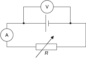
The variable resistor is adjusted and a series of current and voltage readings are taken.
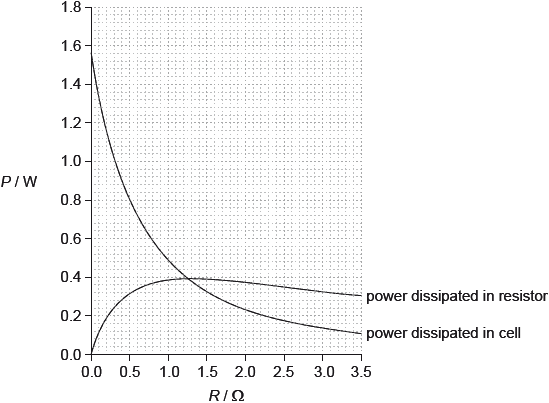
The graph shows the variation with \(R\) of the power dissipated in the cell and the power
dissipated in the variable resistor.
This question is in two parts. Part 1 is about electrical circuits. Part 2 is about magnetic
fields.
Part 2 Magnetic fields
The diagram shows an arrangement for measuring the force between two parallel sections of the same rigid wire carrying a current as viewed from the front.
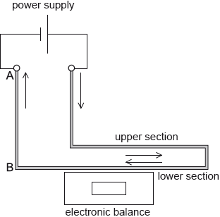
The supports for the upper section of the wire and the power supply are not shown.
When the current in the wire is 0.20 A, the magnetic field strength at the upper section of wire due to the lower section of wire is \(1.3 \times {10^{ - 4}}{\text{ T}}\).
The cell may be damaged if it dissipates a power greater than 1.2 W. Outline why damage in the cell may occur if the terminals of the cell are short-circuited.
The part of the wire from A to B is viewed from above. The direction of the current is out of the plane of the paper.
Using the diagram, draw the magnetic field pattern due to just the current in wire AB.
Deduce what happens to the reading on the electronic balance when the current is switched on.
Calculate the magnetic force acting per unit length on the upper section of wire.
Each cubic metre of the wire contains approximately \(8.5 \times {10^{28}}\) free electrons. The diameter of the wire is 2.5 mm and the length of wire within the magnetic field is 0.15 m. Using the force per unit length calculated in (g)(i), deduce the speed of the electrons in the wire when the current is 0.20 A.
The upper section of wire is adjusted to make an angle of 30° with the lower section of wire. Outline how the reading of the balance will change, if at all.
Markscheme
in this case \(R = 0\) / total resistance is internal resistance;
power dissipated is greater than 1.2 W / power dissipated is 1.56 (W) which is larger than limit; } (must be quantitative not “it’s too big”)
minimum of two concentric circles;
three circles, centered on wire with separation increasing with distance from the wire;
minimum of one arrow showing anticlockwise;
magnetic field due to upper wire on lower wire horizontal and into page;
shows force is downwards by any valid rule; (allow ECF from “out of page”)
reading of balance increases; (allow ECF)
or
currents are antiparallel / in opposite directions;
so wires repelled (by any argument giving force direction);
reading of balance increases;
\(2.6 \times {10^{ - 5}}{\text{ (N}}{{\text{m}}^{ - 1}})\);
volume of wire \( = \pi \times \frac{{{{\left( {2.5 \times {{10}^{ - 3}}} \right)}^2}}}{4} \times 0.15{\text{ }}( = 7.36 \times {10^{ - 7}}{\text{ }}{{\text{m}}^3})\);
charge in wire \( = 8.5 \times {10^{28}} \times 7.36 \times {10^{ - 7}} \times 1.6 \times {10^{ - 19}}{\text{ }}( = 10 \times {10^3}{\text{ C)}}\);
\(v = \frac{F}{{Bq}} = \frac{{3.9 \times {{10}^{ - 6}}}}{{1.3 \times {{10}^{ - 4}} \times {{10}^4}}}\);
\(3.0{\text{ }}\mu {\text{m}}\,{{\text{s}}^{ - 1}}\); (allow ECF from (g)(i))
N.B.: answer should be 0.115 \( \times \) their (g)(i).
Confusing diameter with radius gives answer of 0.75 \(\mu m\,\)s–1 – award [3 max].
Award [4] for a bald correct answer.
parts of the wire will experience a smaller magnetic field;
and hence a smaller force;
so the reading of the balance will decrease / OWTTE;
Examiners report
A considerable lack of thought was in evidence in this part. The correct answer can be stated baldly: a short circuit means that R is zero and therefore the emf of the cell acts on the circuit and the power acting can be read directly from the graph as about 1.5 W. It is greater than 1.2 W and will therefore damage the cell. Few managed to answer in such a direct or convincing way. Most used weasel words that simply repeated the first sentence of the question back to the examiner in an alternative way.
While very many candidates scored a maximum 2 out of 2 marks for this part, this was only because there were 3 marks available. Circles were rarely circular – most were freehand sketches (do modern candidates not possess drawing instruments?). It was rare to see accurate drawings that showed a clear greater line spacing as the distance from the wire increased.
Many scored 2 out to 3 in this part through failing to give the direction rule (first alternative in the mark scheme) by which they assigned the force on the bottom wire. The second alternative attracted maximum marks for many.
This simple calculation was well done. The unit, however, was frequently incorrect (not a marking point).
Only a handful of candidates were able to work this problem through. Significant hurdles for many included: failure to calculate the volume of the wire (not just a radius/diameter confusion, a genuine inability to operate \(l\pi {r^2}\) convincingly), inability to include the charge on the electron correctly, and an apparent misunderstanding of the operating equation with trigonometric functions appearing out of the blue.
Many simply stated the answer without any rigorous explanation of the causal links and therefore scored a generous one mark for what might have been close to a guess (had the option of “no change” not been available).