DP Physics Questionbank

11.2 – Power generation and transmission
| Path: |
Description
Nature of science:
Bias: In the late 19th century Edison was a proponent of direct current electrical energy transmission while Westinghouse and Tesla favoured alternating current transmission. The so called “battle of currents” had a significant impact on today’s society. (3.5)
Understandings:
- Alternating current (ac) generators
- Average power and root mean square (rms) values of current and voltage
- Transformers
- Diode bridges
- Half-wave and full-wave rectification
Applications and skills:
- Explaining the operation of a basic ac generator, including the effect of changing the generator frequency
- Solving problems involving the average power in an ac circuit
- Solving problems involving step-up and step-down transformers
- Describing the use of transformers in ac electrical power distribution
- Investigating a diode bridge rectification circuit experimentally
- Qualitatively describing the effect of adding a capacitor to a diode bridge rectification circuit
Guidance:
- Calculations will be restricted to ideal transformers but students should be aware of some of the reasons why real transformers are not ideal (for example: flux leakage, joule heating, eddy current heating, magnetic hysteresis)
- Proof of the relationship between the peak and rms values will not be expected
Data booklet reference:
International-mindedness:
- The ability to maintain a reliable power grid has been the aim of all governments since the widespread use of electricity started
Theory of knowledge:
- There is continued debate of the effect of electromagnetic waves on the health of humans, especially children. Is it justifiable to make use of scientific advances even if we do not know what their long-term consequences may be?
Aims:
- Aim 6: experiments could include (but are not limited to): construction of a basic ac generator; investigation of variation of input and output coils on a transformer; observing Wheatstone and Wien bridge circuits
- Aim 7: construction and observation of the adjustments made in very large electricity distribution systems are best carried out using computer-modelling software and websites
- Aim 9: power transmission is modelled using perfectly efficient systems but no such system truly exists. Although the model is imperfect, it renders the maximum power transmission. Recognition of, and accounting for, the differences between the “perfect” system and the practical system is one of the main functions of professional scientists.
Directly related questions
- 16N.1.HL.TZ0.33: Which of the following reduces the energy losses in a transformer? A. Using thinner wires for...
-
16N.2.HL.TZ0.10b:
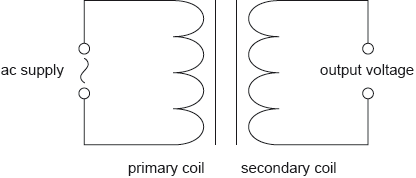
Electrical power output is produced by several alternating current (ac) generators which use transformers to deliver energy to the national electricity grid.
The following data are available. Root mean square (rms) values are given.
ac generator output voltage to a transformer = 25 kV ac generator output current to a transformer = 3.9 kA Transformer output voltage to the grid = 330 kV Transformer efficiency = 96%(i) Calculate the current output by the transformer to the grid. Give your answer to an appropriate number of significant figures.
(ii) Electrical energy is often delivered across large distances at 330 kV. Identify the main advantage of using this very high potential difference.
-
16N.1.HL.TZ0.34:
The secondary coil of an alternating current (ac) transformer is connected to two diodes as shown.
Which graph shows the variation with time of the potential difference VXY between X and Y?
-
16N.2.HL.TZ0.10c:
In an alternating current (ac) generator, a square coil ABCD rotates in a magnetic field.
The ends of the coil are connected to slip rings and brushes. The plane of the coil is shown at the instant when it is parallel to the magnetic field. Only one coil is shown for clarity.
The following data are available.
Dimensions of the coil = 8.5 cm×8.5 cm Number of turns on the coil = 80 Speed of edge AB = 2.0 ms–1 Uniform magnetic field strength = 0.34 T(i) Explain, with reference to the diagram, how the rotation of the generator produces an electromotive force (emf ) between the brushes.
(ii) Calculate, for the position in the diagram, the magnitude of the instantaneous emf generated by a single wire between A and B of the coil.
(iii) Hence, calculate the total instantaneous peak emf between the brushes.
- 17M.2.HL.TZ1.8b.i: Explain, using Faraday’s law of induction, how the transformer steps down the voltage.
-
17M.2.HL.TZ1.8b.ii:
The input voltage is 240 V. Calculate the output voltage.
-
17M.1.HL.TZ1.32:
A direct current (dc) of 5A dissipates a power P in a resistor. Which peak value of the alternating current (ac) will dissipate an average power P in the same resistor?
A. 5A
B.
C.
D.
- 17M.2.HL.TZ2.6e.i: Suggest the advantage of using a step-up transformer in this way.
- 17M.2.HL.TZ1.8c: Outline how energy losses are reduced in the core of a practical transformer.
- 17M.2.HL.TZ1.8d: Step-up transformers are used in power stations to increase the voltage at which the electricity...
-
17M.2.HL.TZ2.6e.ii:
The use of alternating current (ac) in a transformer gives rise to energy losses. State how eddy current loss is minimized in the transformer.
-
17M.2.HL.TZ2.6c:
Calculate the root mean square (rms) current in each cable.
-
20N.1.HL.TZ0.34:
Power is dissipated in a resistor of resistance when there is a direct current in the resistor.
What is the average power dissipation in a resistance when the alternating root-mean-square (rms) current in the resistor is ?
A.
B.
C.
D.
- 20N.1.HL.TZ0.33: Why are high voltages and low currents used when electricity is transmitted over long...
-
20N.2.HL.TZ0.9b(i):
The average power output of the generator is . Calculate the root mean square (rms) value of the generator output current.
-
20N.2.HL.TZ0.9b(ii):
The voltage output from the generator is stepped up before transmission to the consumer. Estimate the factor by which voltage has to be stepped up in order to reduce power loss in the transmission line by a factor of .
-
20N.2.HL.TZ0.9b(iii):
The frequency of the generator is doubled with no other changes being made. Draw, on the axes, the variation with time of the voltage output of the generator.
-
17N.1.HL.TZ0.35:
The ratio for a transformer is 2.5.
The primary coil of the transformer draws a current of 0.25 A from a 200 V alternating current (ac) supply. The current in the secondary coil is 0.5 A. What is the efficiency of the transformer?
A. 20 %
B. 50 %
C. 80 %
D. 100 %
-
17N.1.HL.TZ0.36:
An alternating current (ac) generator produces a peak emf E0 and periodic time T. What are the peak emf and periodic time when the frequency of rotation is doubled?
- 21M.2.HL.TZ1.5a: Explain the role of the diode in the circuit when the switch is at position A.
-
21M.2.HL.TZ2.7a.i:
The primary coil has 3300 turns. Calculate the number of turns on the secondary coil.
-
21M.2.HL.TZ2.7a.iii:
Calculate the current in the primary of the transformer assuming that it is ideal.
-
21M.2.HL.TZ2.7a.iv:
Flux leakage is one reason why a transformer may not be ideal. Explain the effect of flux leakage on the transformer.
-
21M.1.HL.TZ1.35:
A resistor designed for use in a direct current (dc) circuit is labelled “50 W, 2 Ω”. The resistor is connected in series with an alternating current (ac) power supply of peak potential difference 10 V. What is the average power dissipated by the resistor in the ac circuit?
A. 25 W
B. 35 W
C. 50 W
D. 100 W
-
21M.1.HL.TZ2.34:
The graph shows the variation of an alternating current with time in a resistor.
What is the average power dissipated in the resistor?
A.
B.
C.
D.
-
18M.2.HL.TZ1.7e:
Describe the use of transformers in electrical power distribution.
- 18M.1.HL.TZ1.35: The diagram shows a diode bridge rectification circuit and a load resistor. ...
-
18M.2.HL.TZ1.7d:
In a different circuit, a transformer is connected to an alternating current (ac) supply.

The transformer has 100 turns in the primary coil and 1200 turns in the secondary coil. The peak value of the voltage of the ac supply is 220 V. Determine the root mean square (rms) value of the output voltage.
- 18M.1.HL.TZ1.34: The graph shows the variation with time t of the current I in the primary coil of an ideal...
-
18M.1.HL.TZ2.35:
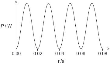
The graph shows the power dissipated in a resistor of 100 Ω when connected to an alternating current (ac) power supply of root mean square voltage (Vrms) 60 V.

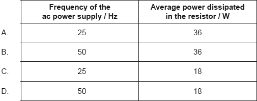
What are the frequency of the ac power supply and the average power dissipated in the resistor?

- 21N.1.HL.TZ0.34: An alternating supply is connected to a diode bridge rectification circuit. The conventional...
-
21N.1.HL.TZ0.35:
The root mean square (rms) current in the primary coil of an ideal transformer is 2.0 A. The rms voltage in the secondary coil is 50 V. The average power transferred from the secondary coil is 20 W.
What is and what is the average power transferred from the primary coil?
-
18N.1.HL.TZ0.34:
The graph shows the variation of the peak output power P with time of an alternating current (ac) generator.
Which graph shows the variation of the peak output power with time when the frequency of rotation is decreased?
-
18N.1.HL.TZ0.35:
A current of 1.0 × 10⁻³ A flows in the primary coil of a step-up transformer. The number of turns in the primary coil is Np and the number of turns in the secondary coil is Ns. One coil has 1000 times more turns than the other coil.
What is and what is the current in the secondary coil for this transformer?
-
18N.2.HL.TZ0.2d.ii:
Determine the peak current in the primary coil when operating with the maximum number of lamps.
- 18N.2.HL.TZ0.2d.i: Outline how eddy currents reduce transformer efficiency.
-
22M.1.HL.TZ1.35:
A direct current in a lamp dissipates power P. What root mean square (rms) value of an alternating current dissipates average power P through the same lamp?
A.
B.
C.
D.
-
22M.1.HL.TZ1.36:
The arrangement shows four diodes connected to an alternating current (ac) supply. The output is connected to an external circuit.
What is the output to the external circuit?
A. Full-wave rectified current
B. Half-wave rectified current
C. Constant non-zero current
D. Zero current
- 22M.1.HL.TZ2.34: Which two features are necessary for the operation of a transformer?
- 19M.1.HL.TZ2.26: The input to a diode bridge rectification circuit is sinusoidal with a time period of 20...
-
19M.1.HL.TZ2.28:
A transformer with 600 turns in the primary coil is used to change an alternating root mean square (rms) potential difference of 240 Vrms to 12 Vrms.
When connected to the secondary coil, a lamp labelled “120 W, 12 V” lights normally. The current in the primary coil is 0.60 A when the lamp is lit.
What are the number of secondary turns and the efficiency of the transformer?
- 19N.1.HL.TZ0.36: A diode bridge rectification circuit is constructed as shown. An alternating potential difference...
