| Date | May 2022 | Marks available | 1 | Reference code | 22M.2.HL.TZ1.8 |
| Level | Higher level | Paper | Paper 2 | Time zone | 1 |
| Command term | Explain | Question number | 8 | Adapted from | N/A |
Question
Two capacitors C1 and C2 of capacitance 28 µF and 22 µF respectively are connected in a circuit with a two-way switch and a cell of emf 1.5 V with a negligible internal resistance. The capacitors are initially uncharged. The switch is then connected to position A.

The switch is moved to position B.
A cell is now connected by a switch to a coil X. A second coil Y of cross-sectional area 6.4 cm2 with 5 turns is looped around coil X and connected to an ideal voltmeter.

The graph shows the variation with t of the magnetic flux density B in coil Y.

Show that the charge stored on C1 is about 0.04 mC.
Calculate the energy transferred from capacitor C1.
Explain why the energy gained by capacitor C2 differs from your answer in (b)(i).
The switch is closed at time t = 0. Explain how the voltmeter reading varies after the switch is closed.
Determine the average emf induced across coil Y in the first 3.0 ms.
Markscheme
«» = 0.042 «mC» ✓
Award MP for full replacement or correct answer to at least 2 significant figures.
«J» ✓
total capacitance = 50 «μF»
OR
pd = «» 0.84 «V»
OR
charge on C1 after switch moved to B = 0.0235 «mC» ✓
«J» ✓
energy lost «μJ» ✓
energy transferred to electromagnetic radiation «to environment»
OR
energy is transferred as thermal energy / heat «to circuit components» ✓
initial deflection by voltmeter falling to zero reading ✓
emf is induced «only» while the field / flux is changing ✓
attempted use of OR ✓
✓
8.0 «mV» ✓
Examiners report
This was a "show that" question, and it was very well done by most candidates.
This question was challenging for many candidates. A large number successfully calculated the initial energy of C1, but then seemed confused about the next steps. Few candidates successfully calculated the energy in C1 after the switch was closed. There was an ECF opportunity for candidates who recognized that the final answer was the difference between these two values.
This question used an "explain" command term, so examiners were looking for more than a generic "energy was lost". Candidates needed to specify a form of energy that was lost (such as thermal energy) for the mark. A very common incorrect response was simply stating that the difference was due to the capacitors having a different capacitance.
This question was well answered by some candidates who recognized that it was an electromagnetic induction question and understood that eventually the current in coil X would hit a steady state and the voltmeter reading would return to zero. Common issues were candidates thinking that the potential would fluctuate in a manner similar to an alternating current, candidates discussing this more as a transformer, and candidates who missed that there were two separate coils and wrote responses suggesting that a simple circuit had been formed and the voltmeter would read the potential of the cell.
This question was well approached with most candidates recognizing that this was a Faraday's law question. Many made an attempt to use the correct equation, but common errors were choosing incorrect values from the graph and incorrectly converting the given area. Examiners were generous with ECF for candidates who clearly showed work leading to an incorrect result.
Syllabus sections
-
17N.1.HL.TZ0.37:
Six identical capacitors, each of value C, are connected as shown.

What is the total capacitance?
A.
B.
C.
D. 6C
- 19M.1.SL.TZ1.20: Two charges, +Q and −Q, are placed as shown. What is the magnitude of the electric field...
-
18M.2.HL.TZ1.7c:
The capacitor is fully charged and the space between the plates is then filled with a dielectric of permittivity ε = 3.0ε0.
Explain whether the magnitude of the charge on plate A increases, decreases or stays constant.
-
18M.2.HL.TZ1.7b:
The capacitor is connected to a 16 V cell as shown.
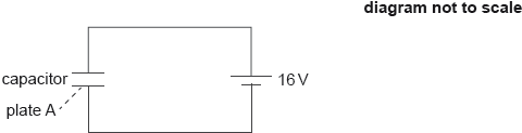
Calculate the magnitude and the sign of the charge on plate A when the capacitor is fully charged.
-
18M.2.HL.TZ2.8d:
State one assumption that needs to be made so that the Earth-thundercloud system may be modelled by a parallel plate capacitor.
- 22M.1.HL.TZ2.36: A circuit consists of three identical capacitors of capacitance C and a battery of voltage V....
- 19M.1.HL.TZ1.36: Two capacitors of 3 μF and 6 μF are connected in series and charged using a 9 V...
- 22M.1.HL.TZ1.37: Three identical capacitors are connected together as shown. What is the order of...
- 17M.1.HL.TZ2.36: A fully charged capacitor is connected to a resistor. When the switch is closed the capacitor...
- 16N.1.HL.TZ0.36: Three capacitors are arranged as shown. What is the total capacitance of the...
- 17M.1.HL.TZ2.35: Two capacitors of different capacitance are connected in series to a source of emf of...
- 18N.2.HL.TZ0.7c: An additional identical capacitor is connected in series with the first capacitor and...
- 18N.2.HL.TZ0.7a: The battery has an emf of 7.5 V. Determine the charge that flows through the motor when the...
-
19N.2.HL.TZ0.9b(ii):
Calculate the final total energy, in J, stored in X and Y.
-
19M.2.HL.TZ1.8b.i:
The resistor R in the circuit has a resistance of 1.2 kΩ. Calculate the time taken for the charge on the capacitor to fall to 50 % of its fully charged value.
- 19M.2.HL.TZ2.4dii: Suggest, in terms of conservation of energy, the cause for the above change.
-
18M.2.HL.TZ2.8c.i:
Show that about –11 C of charge is delivered to the Earth’s surface.
-
19M.1.HL.TZ2.27:
Three identical capacitors are connected in series. The total capacitance of the arrangement is mF. The three capacitors are then connected in parallel. What is the capacitance of the parallel arrangement?
A. mF
B. 1 mF
C. 3 mF
D. 81 mF
- 17N.1.HL.TZ0.38: A capacitor of capacitance C discharges through a resistor of resistance R. The graph shows...
-
19M.2.HL.TZ2.4di:
Calculate the change in the energy stored in the capacitor.
-
19N.2.HL.TZ0.9c:
Suggest why the answers to (a) and (b)(ii) are different.
- 16N.1.HL.TZ0.35: A parallel-plate capacitor is connected to a battery. What happens when a sheet of dielectric...
-
19M.1.HL.TZ1.37:
The circuit diagram shows a capacitor that is charged by the battery after the switch is connected to terminal X. The cell has emf V and internal resistance r. After the switch is connected to terminal Y the capacitor discharges through the resistor of resistance R.

What is the nature of the current and magnitude of the initial current in the resistor after the switch is connected to terminal Y?

- 21N.2.HL.TZ0.3c.i: At t = 0, the switch is connected to X. On the axes, draw a sketch graph to show the...
- 19M.2.HL.TZ1.8a.ii: The plastic film begins to conduct when the electric field strength in it exceeds 1.5 MN C–1....
-
18N.1.HL.TZ0.36:
Four identical capacitors of capacitance X are connected as shown in the diagram.

What is the effective capacitance between P and Q?
A.
B. X
C.
D. 4X
- 17M.1.HL.TZ1.34: A battery is used to charge a capacitor fully through a resistor of resistance R. The energy...
- 17M.1.HL.TZ1.35: A capacitor is charged by a constant current of 2.5 μA for 100 s. As a result the potential...
- 18M.1.HL.TZ1.36: A parallel plate capacitor is connected to a cell of negligible internal resistance. ...
- 19N.1.HL.TZ0.35: A capacitor of capacitance 1.0 μF stores a charge of 15 μC. The capacitor is discharged...
-
18M.2.HL.TZ2.8b.i:
Calculate in V, the potential difference between the thundercloud and the Earth’s surface.
-
18M.2.HL.TZ2.8a:
Show that the capacitance of this arrangement is C = 6.6 × 10⁻⁷ F.
-
19N.2.HL.TZ0.9a:
Calculate, in J, the energy stored in X with the switch S open.
- 21M.2.HL.TZ1.5b.iii: Identify, using the label + on the diagram, the polarity of the capacitor.
-
21M.2.HL.TZ1.5b.ii:
Calculate the maximum charge Q0 stored in the capacitor.
- 21M.2.HL.TZ1.5c.i: Describe what happens to the energy stored in the capacitor when the switch is moved to...
-
21M.2.HL.TZ1.5c.ii:
Show that the charge remaining in the capacitor after a time equal to one time constant of the circuit will be 0.37 Q0.
-
21M.2.HL.TZ1.5c.iii:
The graph shows the variation with time of the charge in the capacitor as it is being discharged through the heart.

Determine the electrical resistance of the closed circuit with the switch in position B.
- 21M.2.HL.TZ1.5d: In practice, two electrodes connect the heart to the circuit. These electrodes introduce an...
-
21M.2.HL.TZ1.5b.i:
Show that the maximum energy stored by the capacitor is about 160 J.
-
21M.1.HL.TZ1.36:
A capacitor of capacitance X is connected to a power supply of voltage V. At time t = 0, the capacitor is disconnected from the supply and discharged through a resistor of resistance R. What is the variation with time of the charge on the capacitor?
-
19N.2.HL.TZ0.9b(i):
Calculate the final charge on X and the final charge on Y.
-
18N.2.HL.TZ0.7b:
The motor can transfer one-third of the electrical energy stored in the capacitor into gravitational potential energy of the mass. Determine the maximum height through which a mass of 45 g can be raised.
-
21M.1.HL.TZ2.36:
A capacitor is charged with a constant current . The graph shows the variation of potential difference across the capacitor with time . The gradient of the graph is . What is the capacitance of the capacitor?

A.
B.
C.
D.
- 21M.1.HL.TZ2.33: A parallel-plate capacitor is connected to a cell of constant emf. The capacitor plates...
-
20N.1.HL.TZ0.36:
A capacitor of capacitance has initial charge . The capacitor is discharged through a resistor of resistance . The potential difference across the capacitor varies with time.
What is true for this capacitor?
A. After time the potential difference across the capacitor is halved.
B. The capacitor discharges more quickly when the resistance is changed to .
C. The rate of change of charge on the capacitor is proportional to .
D. The time for the capacitor to lose half its charge is .
- 18M.1.HL.TZ2.36: Three capacitors, each one with a capacitance C, are connected such that their...
-
17M.2.HL.TZ2.3a:
The capacitance of the capacitor is 22 mF. Calculate the energy stored in the capacitor when it is fully charged.
-
17M.2.HL.TZ2.3b:
The resistance of the wire is 8.0 Ω. Determine the time taken for the capacitor to discharge through the resistance wire. Assume that the capacitor is completely discharged when the potential difference across it has fallen to 0.24 V.
-
18M.2.HL.TZ2.8b.ii:
Calculate in J, the energy stored in the system.
-
18M.2.HL.TZ1.7a:
Calculate the distance between the plates.
-
19M.2.HL.TZ2.4c:
The cell is used to charge a parallel-plate capacitor in a vacuum. The fully charged capacitor is then connected to an ideal voltmeter.

The capacitance of the capacitor is 6.0 μF and the reading of the voltmeter is 12 V.
Calculate the energy stored in the capacitor.
-
19M.2.HL.TZ1.8a.i:
Calculate the total length of aluminium foil that the student will require.
-
21N.1.HL.TZ0.36:
Two initially uncharged capacitors X and Y are connected in series to a cell as shown.

What is ?
A.B.
C.
D.
-
21N.2.HL.TZ0.3c.ii:
The switch is then connected to Y and C discharges through the 20 MΩ resistor. The voltage Vc drops to 50 % of its initial value in 5.0 s. Determine the capacitance of C.
-
22M.2.HL.TZ1.8a:
Show that the charge stored on C1 is about 0.04 mC.
-
22M.2.HL.TZ1.8b.i:
Calculate the energy transferred from capacitor C1.