| Date | November 2010 | Marks available | 4 | Reference code | 10N.2.HL.TZ0.B2 |
| Level | Higher level | Paper | Paper 2 | Time zone | Time zone 0 |
| Command term | Calculate | Question number | B2 | Adapted from | N/A |
Question
This question is in two parts. Part 1 is about a lightning discharge. Part 2 is about microwave radiation.
Part 2 Microwave radiation
A microwave transmitter emits radiation of a single wavelength towards a metal plate along a line normal to the plate. The radiation is reflected back towards the transmitter.
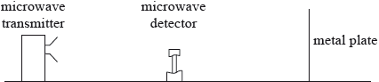
A microwave detector is moved along a line normal to the microwave transmitter and the metal plate. The detector records a sequence of equally spaced maxima and minima of intensity.
The microwave detector is moved through 130 mm from one point of minimum intensity to another point of minimum intensity. On the way it passes through nine points of maximum intensity. Calculate the
Explain how these maxima and minima are formed.
(i) wavelength of the microwaves.
(ii) frequency of the microwaves.
Describe and explain how it could be demonstrated that the microwaves are polarized.
Markscheme
standing wave formed;
by superposition/interference of (forward) wave and reflected wave;
maximum where interference is constructive / minimum where interference is destructive;
maxima where waves in phase;
minima where waves are completely/180°/\(\pi \)/half wavelength out of phase;
(i) \({\text{130 mm}} \equiv {\text{9 half wavelengths}}\);
29 mm;
(ii) \(f = \frac{c}{\lambda }\);
\( = 10{\text{ GHz}}\);
place a metal grid/analyser between source and detector;
electric field vector (of the microwaves) vibrates in only one direction/plane;
rotate the metal grid/detector;
until minimum signal is detected;
or
electric field vector vibrates in only one direction/plane;
rotate transmitter through an angle;
need to rotate receiver through same angle to restore signal in transmitter;
Examiners report
Few were able to give complete and convincing explanations of the formation of the standing wave. Common errors were to omit the consequence of the reflection at the metal plate. Superposition was often poorly or even not described. Details of the phase relationships were also poor.
(i) and (ii) Candidates were very comfortable with these calculations although the number of wavelengths in (i) was often incorrect. Errors from (i) were carried forward to (ii) allowing many cases of full credit in this second part.
Examiners saw very few good descriptions of the polarization demonstration. A number of techniques are available but it is clear that candidates have either not discussed these or find the concept difficult.