| Date | November 2015 | Marks available | 2 | Reference code | 15N.2.HL.TZ0.8 |
| Level | Higher level | Paper | Paper 2 | Time zone | Time zone 0 |
| Command term | Outline | Question number | 8 | Adapted from | N/A |
Question
Part 2 Power transmissions
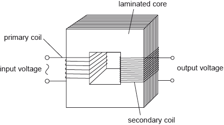
The diagram shows the main features of an ideal transformer whose primary coil is connected to a source of alternating current (ac) voltage.

A different transformer is used to transmit power to a small town.

The transmission cables from the power station to the transformer have a total resistance of 4.0 Ω. The transformer is 90% efficient and steps down the voltage to 120 V. At the time of maximum power demand the effective resistance of the town and of the cables from the transformer to the town is 60 mΩ.
Outline, with reference to electromagnetic induction, how a voltage is induced across the secondary coil.
The primary coil has 25 turns and is connected to an alternating supply with an input voltage of root mean squared (rms) value 12 V. The secondary coil has 80 turns and is not connected to an external circuit. Determine the peak voltage induced across the secondary coil.
Calculate the current in the cables connected to the town
Calculate the power supplied to the transformer.
Determine the input voltage to the transformer if the power loss in the cables from the power station is 2.0 kW.
Outline why laminating the core improves the efficiency of a transformer.
Markscheme
(alternating) pd/voltage across primary coil leads to (alternating) current (in primary coil);
hence there is a changing/alternating magnetic field in primary;
leading to a changing magnetic flux linked to/appearing in secondary;
according to Faraday’s law, an alternating emf is induced in the secondary coil;
rms secondary voltage \( = 38.4{\text{ (V)}}\);
peak voltage \( = \left( {38\sqrt 2 = } \right){\text{ 54 (V)}}\); (allow ECF from MP1)
Award [2] for a bald correct answer.
\(\left( {{I_{\text{s}}} = \frac{{120}}{{60 \times {{10}^{ - 3}}}}} \right) = 2.0{\text{ k(A)}}\); (30 A is a common and incorrect answer)
power (supplied to town) \( = 2.0 \times {10^3} \times 120\)\(\,\,\,\)or\(\,\,\,\)\(2.4 \times {10^5}\); (allow ECF from (f)(i))
power (supplied to transformer) \(\left. { = \left( {\frac{{2.4 \times {{10}^5}}}{{0.9}} = } \right){\text{ }}2.67 \times {{10}^5}{\text{ (W);}}} \right\}\) (30 A in (f)(i) leads to 4 kW)
Award [2] for a bald correct answer.
\({I_{\text{p}}} = \sqrt {\frac{{2 \times {{10}^3}}}{{4.0}}} = 22.4{\text{ (A)}}\);
\(V = \frac{P}{I} = \frac{{2.67 \times {{10}^5}}}{{22.4}} = 12{\text{ k(V)}}\);
Allow ECF from (f)(i) and (f)(ii).
30 A and 4 kW earlier leads to 179 V.
Award [2] for a bald correct answer.
laminations increase resistance / reduce current in core material/metal / reduce eddy currents;
thus reducing \({I^2}R\)/power/(thermal) energy/heat losses in the core;
Examiners report
In the second part of this question, candidates showed themselves to be much less confident with ideas of electromagnetic induction. Discussion of induction of the secondary emf in the transformer ought to be well rehearsed and confident from a candidate at this level. Instead, examiners were treated to incomplete and often non-physical descriptions. Standard and expected terminology was rare. Terms such as magnetic flux, linking, emf and induction were either omitted or misused. This is clearly an area where there is much misunderstanding.
On the other hand, candidates were well able to cope with the (straightforward) calculation of the induced emf across the secondary coil. However, a frequent omission was the final conversion to a peak value.
This whole sequence of calculations was poorly done. Candidates appear never to have considered the problem of energy loss in the cabling between energy generator and consumer. This ought to be straightforward work for the candidates, but it proved not to be. Solutions as a whole were confused with little clear explanation of what was going on. Candidates were evaluating the wrong quantities without realising it and then misapplying them later in the question. As an example, simply labelling a quantity as “Power =…” is unhelpful. What power is being referred to by the candidate? The argument must be clear in order that an examiner can award error carried forward.
This whole sequence of calculations was poorly done. Candidates appear never to have considered the problem of energy loss in the cabling between energy generator and consumer. This ought to be straightforward work for the candidates, but it proved not to be. Solutions as a whole were confused with little clear explanation of what was going on. Candidates were evaluating the wrong quantities without realising it and then misapplying them later in the question. As an example, simply labelling a quantity as “Power =…” is unhelpful. What power is being referred to by the candidate? The argument must be clear in order that an examiner can award error carried forward.
This whole sequence of calculations was poorly done. Candidates appear never to have considered the problem of energy loss in the cabling between energy generator and consumer. This ought to be straightforward work for the candidates, but it proved not to be. Solutions as a whole were confused with little clear explanation of what was going on. Candidates were evaluating the wrong quantities without realising it and then misapplying them later in the question. As an example, simply labelling a quantity as “Power =…” is unhelpful. What power is being referred to by the candidate? The argument must be clear in order that an examiner can award error carried forward.
Many had rote learnt the first point about laminations in a transformer core: that the eddy currents are reduced. However, a good candidate will realise that the nature of the core must mean that they are never entirely eliminated – complete elimination of the currents was a common and incorrect answer.

